
Late in 1998, Don Wallace of Ottawa emailed me with the following request.
_____________________________________________
Date: Thu, 12 Nov 1998 13:35:23 +1000
To: Joseph Cali <joe.cali@anu.edu.au>
Subject: Re: spotmeter as a densitometer
Cc:
Bcc:
X-Attachments:
Joe:
I read that you calibrated your spotmeter as a densitomer. Can you tell me how to do this?
Don Wallace
Ottawa, Canada
_____________________________________________
Introduction
It is important to note that I haven't calibrated my system for
the whole density range. I only need to measure base + fog densities
for optimising hypersensitising times. When I calibrated
my spotmeter, I only calibrated it at densities between 0 and
0.8. My application only requires measuring densities between
0 and 0.8 only. Extrapolating the calibration line to a density
of 3.2, the meter has plenty of dynamic range to cope with this
density range. The trick is to have a standard light source which
is the appropriate intensity to
This description does describe how to calibrate the entire density range. I've tried not to leave anything out. Don't be put off. It's remarkably simple to do but naturally not quite as accurate as a professional densitometer. I was however pleasantly surprised. It works much better than I expected for the cost of half a roll of film, some density measurements at your local prolab and a sheet of graph paper. I've included my calibration graph at the end of this description.
Design considerations
My calibration was actually several evenly lit frames of 35mm B&W film. My only interest was to measure base density levels so I can't vouch for the system for measuring very dense negs for something like a zone system development test. It may require that you use a bright light source and/or perform two calibrations - one with a bright light for high density and one with a fainter light for low density.
Why does this work?
Most meters have a 20 eV measuring range. Each eV corresponds
to a doubling or halving of the light level. If you remember back
to early high school, this is a base 2 logarithm. Photographic
density is a base 10 logarithm. It isn't essential that you understand
the maths to perform this calibration.
A photographic density range of 3.05- 0.05 represents a change in light level of
ALOG10 (3.05-0.05) = 1000
Using the lightmeter eV measurement
ALOG2(9.965 eV) = 1000.
Providing the light souce is bright enough that the density of clear film records more than 10ev above the meters minumum sensitivity, you should be able to measure the full density range with that meter providing it has a dynamic range greater than 10 eV. If the meter has a typical range of ~20eV, the task becomes much simpler. The slope of the calibration curve can be predicted as follows.
SLOPE = (Dmax-Dmin) / (eVmin-eVmax )
Where
Dmax - Dmin = 3.05 0.05 = 3
and
eVmin eVmax = -9.965eV
from this it foillows that the
Theoretical slope of the calibration line ~ 3.3
Make or buy a Calibrated Step tablet
You can buy an uncalibrated or for a greater cost, a calibrated step tablet from Kodak with 21 different density steps ranging from 0.05 to 3.05. The uncalibrated tablet is Kodak Photographic step tablet No 3. Cat # 1523414
You can make your own calibration frames by exposing some fine grained B&W film as follows. The exposures must be out of focus exposures of an evenly lit plain surface.
If you want to get a full density range step tablet, expose in 1/2 stop increments from - 8 stops to +8 stops. Use Tech pan 2415 (The 2415 must be developed in technidol for this application) so that the lowest calibrated density is less than or equal to the minimum you will need. When taking these exposures, make your self at least 5 frames of the "correctly exposed" and the "-8 stop" frames as you will use these frequently as calibration standards.
Note that this negative strip will only suffice as a calibration standard for your densitometer and does not replace the function of a step tablet in sensitometry.
I have a friend who works, restoring very old movie films, at Film & Sound Australia. He measured those same frames on a microdensitometer for me. Any full service pro lab will do density measurements for you for a small fee or sometimes for free if they develop the film for you (Remember - this is just a density calibrating standard not a way of calibrating your zone system development).
Making the densitometer
Make a small light box with a movable 100W tungsten pearl lamp and some opalescent perspex as a lid. Fig 1 Punch a small hole (3mm) in a piece of card or aluminium(hole diameter isn't important) and measure all frames with the spotmeter (I use a Sekonic L-318) through the small hole using the eV measurement scale.
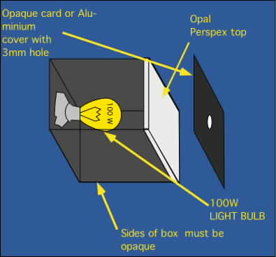
| Figure 1. A simple design for a densitometer. The tunnel should be much longer than shown and the light source should be able to move relative to the perspex top. A cooling fan blowing air in near the perspex will prevent meltdown. |
Making measurements for the calibration
The eV measurement on a light meter works on a logarithmic scale just like film density so the resulting eV-density calibration line is linear. My notebook will re-emerge from the cartons it is packed in in 8-10 weeks time so if necessary I can check later.
Measure the surface brightness of the lightbox. If the brightness isn't even, ensure that the measurements are always made on the same part of the box. The easiest way to achieve this is to hinge the hole plate to the perspex. Record the brightness.
Measure all the different density negatives by measuring the eV reading through the small hole with your light meter. Make sure the light is even and mark the distance from the light source to the perspex sheet so you can get the same brightness later.
Plot your calibration line on a large piece of 1mm ruled graph paper eV on the horizontal axis, density on the vertical. This graph correlates film density to eV measurements made with your light meter through the hole in the piece of card. You can also do this on a computer and calculate the regression line.
Measuring densities.
You have five base & five middle grey calibration negatives along with the various other densities. Put 4 of each away in a safe place. These are extras so that as they get scratched or damaged, you can discard them and you will have spares. Mount them in 36mm glassless slide holders for protection.
Before you begin each measuring session, check the eV readings of the surface brightness of the lightbox. If it is different to the one used during the calibration, change the distance of the lightbulb from the perspex until it is the same as recorded during the calibration.
To check that the density calibration is correct measure the eV on one unexposed & one middle grey slide. If the readings differ from the readings made in your original calibration, move the lamp closer to or further from the perpex screen until the readings match. There are multiple slides of these types because you will scratch or damage these due to the amount of use they will get. Do not use glass mounts as the glass may add extra density unless you measure the density of the film in the glass mount.
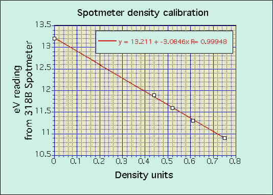
Make a measurement on your piece of film. Read from the calibration curve (figure 2) the density & voila, you have a densitometer.
|
|
Note that the regression equation has a slope of -3.08. A value of -3.3 was predicted from theory. The intercept of the line on the eV axis is simply the eV value of the lightbox surface. Before use, adjust the distance of the light from the perspex screen until this value matches the value you got in your calibration, then measure a middle grey or a very dense slide to ensure that the slope is also identical. This procedure should take less than a minute and assures reproducibility.
My light meter is accurate to +/-0.1 eV. Hence the expected accuracy of the density measurements is +/- 0.03 density units.